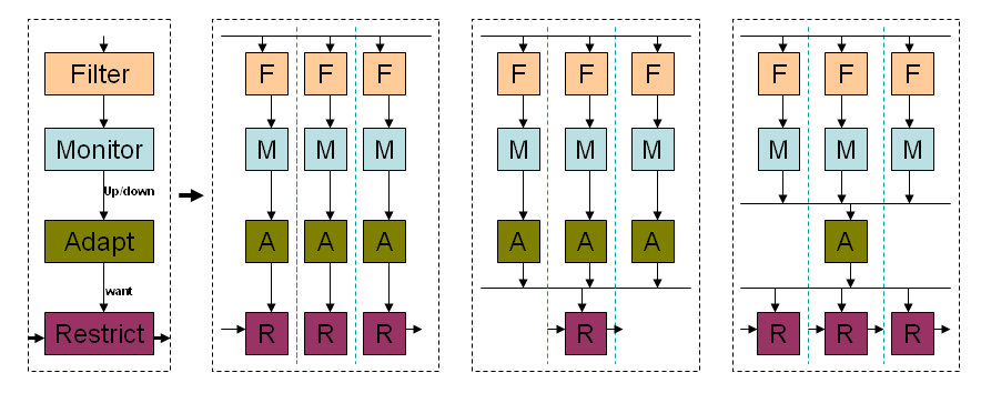
multiple:
multiple with single Adaptor:
The distributing and merging of signals is far more complex than it first seems!!!
This page is an artistic ramble through some issues that you may encounter when taking a single adaptive system to a distributed adaptive system.
It is not rigourous and jumps about as the thought come to mind. Enjoy!!!
Lets start with the well known integrator using a virtual ground op-amp.
Consider the circuit below:
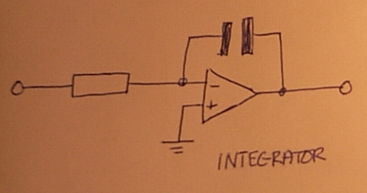
This is a standard integrator.
The output adapts until Vinput+ equals Vinput- helped by the high gain of the Amplifier.
The Op amp has a high gain, Voutput = Gain x ( Vinput+ minus Vinput- )
The current flowing into the input has no where to go except into the Capacitor. The Voltage across the capacitor increases proprotional to the input current. The output voltage adapts so that Vinput- equals Vinput+.
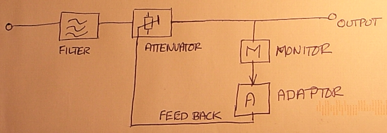
Consider the diagram below, of a simple adaptive attenuator e.g an automatic volume control:
The output is adapted. The monitor measures the output and using the adaptor, the feed back is sent back to the attenuator or restrictor.
Here are some building blocks.
Filters:-
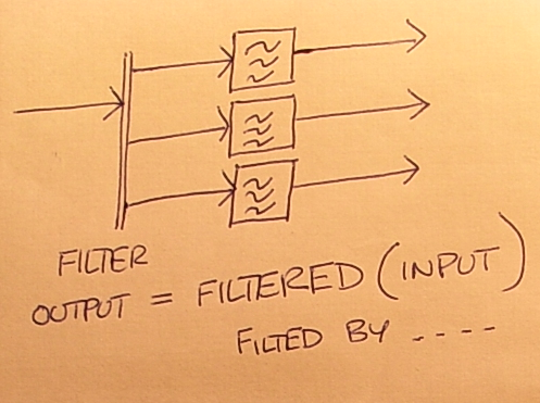
Filters can filter in a number of domains - frequency, type of events. They select some events out of the input stream. Consider if the filters overlap - are some events admitted by more than one filter? What happens if a filter does not admit the event? What happens if no filter admits an event?
[spectrum Analyser]-http://www.dougrice.plus.com/hp/Theory/indexCG.htm
Load Share:-
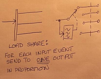
A stream has to be shared out to only one destination in proportion. In this case, the event cannot be duplicated.
Simple single Adaptation device:-
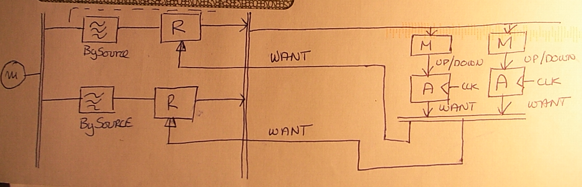
Multi Variable or distributed Adaptation:-
Above the input is filtered into streams and restricted by restrictor,R. The restricted streams are combined to form OUTPUT.
The monitor,M works out if the output needs more or less. The Monitor,M input can also be filtered to select certain events.
Based on the OUTPUT level, it works out an UP/DOWN signal to drive an adaptor,A
Integration can be achieved by a timer maturing and using the UP/DOWN signal to add or subtract a quantity to the feedback level called WANT. This could use classic Proportional, Integral, Differential, PID to calculate WANT.
The Adaptor,A integrates the UP/DOWN signals to work out the feedback required. This is expressed as WANT. The problem is sometimes only one WANT value signal can be used.
The restrictor,R uses the feed back to attenuate the input signal more or less.
In the diagram above there are two adaptors both producing WANT. Is this possible?
Does WANT from one adaptor conflict with the WANT from the other Adaptor?
This depends on how WANT is implemented and combined or chossen.
Is WANT summed or choosen by magnitude or the last WANT calculated?
Both Adaptors could work out their WANT and send it to restrictor,R, which uses the last value received. What does this would mean to the average restriction. Would one adaptor dominate?
e.g WANT may be a value that is writing into a double buffered DtoA converter or digital potentiometer.
The last WANT written would be used.
It may conflict and the last updated value over writes the other Adaptor's WANT value, and there is a conflict.
There are a number of choices of how the Adaptors,A combine or choose the WANT to be used by the restrictor,R
Lets assume R is a digital Attenuator set by sending WANT as a single numerical value.
There needs to be a clarification if the 'wires' above carry events or levels. Do the events carry a level, and the WANT is updated but not integrated.
Are we talking about rates as measured in events per second or levels. Are the levels integrated into rate by sampling periodically to level * ticks per second.
If the restrictor,R updates as WANT changes, there will be an average WANT per second.
If the restrictor,R changes when it is clocked by it's own clock, the average WANT per second is dependent on this clock and how WANT changes. It maybe that the clock is not a constant tick.
Restrictor,R could be a monostable that blocks events and WANT controls the timeout of the monostable. The value of WANT is used as the timeout when triggering the monostable.
The diagram needs lines drawn expressing the units.
Are the sampling rates constant or variable? They could be both and different.
Lets assume events are a stream of cars classified by colour.
We can plots a spectrum of the average car colour. Y-Axis is number of cars, X axis ranked by colour.
The restrictor could have units of car colour, that is the filter admits only cars of specific colour, and R admits a percentage of cars. R could be design to limit a rate of cars per second.
The filter could be more specific. It could be Car colour and Car Make. It could be Car Name and number of passangers. Units!!!
The filter could be more specific. It could be Car colour and Road. It could be Car Name and number of passangers. Units!!!
Units are important. At School, our Physics master stressed we should check the units in our calculations.
The diagram shows "filter by source".
Say, the input has units of Cars per second, but split into sources so the units are Cars per second per source.
We have a stream of cars, approaching a major bridge, there are a number of approach roads, or sources. We want to adapt the rate of cars using the bridge.
The restrictor needs to have WANT expressed as CARS per Second per road. The output of the restrictor is combined back to a total so the units become Cars per second.
Does WANT need to be converted to WANT per road?
WANT could have the units of percentage, Cars, or Cars per road.
We have have a total expressed as CARS, and streams expressed as CARS per road.
Kirchoff has a current law, the sum of currents into a node equals zero. Is there an equivalent here?
Does total WANT need to use the same units as OUTPUT is measured in. Could it be a function? It may be forced to be a function.
The diagram needs the notation explained.
The Op Amp used levels - current and voltages.
We could have a system that uses events, and these need combining.
Elsewhere on this web site are buss bars combining and distributing signals and events.
The output combines the input. Here is a list of a number of ways this could happen. We need a way to notate this.
* receive from: SUM , MAX( list ) , MIN ( list ), MERGE, IN_ORDER, IN_TURN, SELECT, REQUESTED, INVITED, POLLED, LAST_RECEIVED, LAST_UPDATED
We can pick one of. :
We can accumulate:
The outputs are based on the input. Here is a list of a number of ways this could happen. We need a way to notate this.
Kirchoff i.e. input rate equal to sum of Output rates
* send to: ONE_OF, SHARE, DEAL, IN_TURN, LOAD SHARE, TRY_IN_ORDER
Non Kirchoff i.e. input rate Not equal to sum of output rates
* send to: ALL, REPLICATE, PUBLISH_&_POLLED
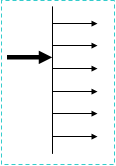
We can send to:
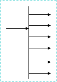
We can broadcast:
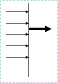
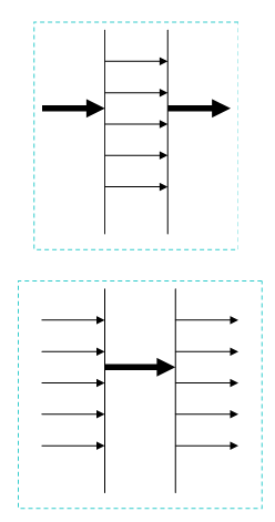
Combine and distribute:
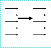
Distribute and combine:
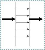
Take the input, filter it, monitor it, adapt a value and use it to control the attentuator or restrictor.
Consider making this distrubuted and work out which to distribute.
What problems are there using the outputs for the next block?
Here are a few ideas to consider and express and constrain.
![[Home]](../ipstats.gif)