These are fun to experiment with.
I did a schools day at work where we had to help the school pupils code a simple line follower.
The day taught tinkering and simple coding and uploading code to the cart or buggy.
It also involved team work.
At the end of the day, there was a race between the different teams.
Well worth it.
There are many strategies the cards can use.
.jpg)
Line Follower Cart Toy Fire Engine

This little line follower toy has two Infrared sensors and two motors.
If the sensor sees bright, it powers the motor.
The sensor on the left controls the left motor.
The sensor on the right controls the right motor.
If both are dark it stops.
It came with a felt tip pen to draw a line on a bit of paper.
If you aim it at a black line at an angle, it turns and then wobbles down the line.
| sensor_left | sensor_right | motor_left | motor_right | direction |
| dark | dark | off | off | stops |
| dark | bright | off | on | turns to left |
| bright | dark | on | off | turns to right |
| bright | bright | on | on | forward |
This worked. You could draw a line with a hammer head and it would follow it and stop at the hammer head.
eBay had a line follower cart kit. It was worth buying for the two motors and a bit of fun.
DIY Smart Robot Car Electronic Assembly Kit Set With-Reduction Motors
https://www.ebay.co.uk/itm/143755630164
It has two motors and a two light sensors and LEDS and a LM393 comparator.
The circuit:
.jpg)
There are two comparators, one for each motor, but the + and - inputs are wired contra making it look like a comparator with an inverter on the output.
.png)
If they are comparators, then only one motor would be powered up, but when the Light Dependent Resistors are dark, both motors are running!
This means they are more than comparators.
We can put together this truth table.
| sensor1 | sensor2 | motor1 | motor2 |
| dark | dark | on | on |
| bright | brighter | off | on |
| brighter | bright | on | off |
The comparator needs the inputs to be about 1.5V below the positive supply to act as a comparator.
When well illuminated the Light dependent resistors are low resistance and the voltage on the +ve and -ve pins of the comparator are less than Vcc-1.5V, so act as comparators.
It is important to consider the comparator circuit.
https://www.ti.com/product/LM393
The LM393 uses an open collector output that sinks current to turn on the motor.
The comparator needs the inputs to be between 0V and (Vcc-minus) 1.5V below the positive supply.
When the Light Dependent Resistors are dark, both motors are running.
The +ve and -ve inputs rise to within 2V of the Positive rail, and the output goes low, turning on the motor.
Looking at the circuit, I was worried about R9 and R10 being 10 ohms.
If the drive transistors are wired common emitter, Vbe drops 0.7V max.
Assuming that the op-amps turn on hard , you could get about 220mA!
( VBat - DriveVbe - OpAmpVsat ) / 10 ohms = 220mA !
( 3V - 0.7V - 0.1 V ) / 10ohms would be 220mA.
I swapped the 10 Ohm resistors to 220 Ohm, but I did not understand the circuit of the LM393 comparator at the time.
However, when the LM393 is powered up on a breadboard, with a 5V supply, and and +ve and -ve inputs floating, the output pin sinks about 25mA limited by the 80uA and gain of the ouput transistor inside the LM393.
R9 and R10 at 10 ohms would be okay!
We can put together this truth table.
| sensor1 | sensor2 | motor1 | motor2 |
| dark | dark | on | on |
| bright | brighter | off | on |
| brighter | bright | on | off |
There are two trim pots to adjust for battery voltages, and ambient light levels.
Make sure it turns in circles on a bright surface, and goes straight on dark surface.
When using old rechargeable batteries, I found that the motors stall when I power on. I have to help the wheels to rotate to stop the high current that stops the LEDS from illuminating.
Now the fun starts!
You do not need to follow a line. Othe shapes cause the dirction to be changed.
I found a picture frame with a strong graphic contact and it had a lot of fun exploring the dark blue areas and going around in circles on the white borders.
The two illuminating LEDs could be more robustly attached. I welded / soldered them to the PCB and knocked them and lifted the PCB tracks.
If I have put a blob of solder on the top of the PCB, or bent the LED leads over it would be more robust. You may need to adjust the height. It comes with a bolt with a shiny round nut that can be used to trim the height.
I soldered the kit and it worked and followed the test track on the A4 instruction sheet.
All the instructions were in Chinese.
An iPad was used to translate the Chinese. iPads Translate App came to the rescue.
You can scan the instructions with the camera and used OCR to read the Chineese characters.
Well worth the money. It could be entertaining and fun.
https://www.ebay.co.uk/itm/143755630164
Please see the TI datasheet: https://www.ti.com/product/LM393
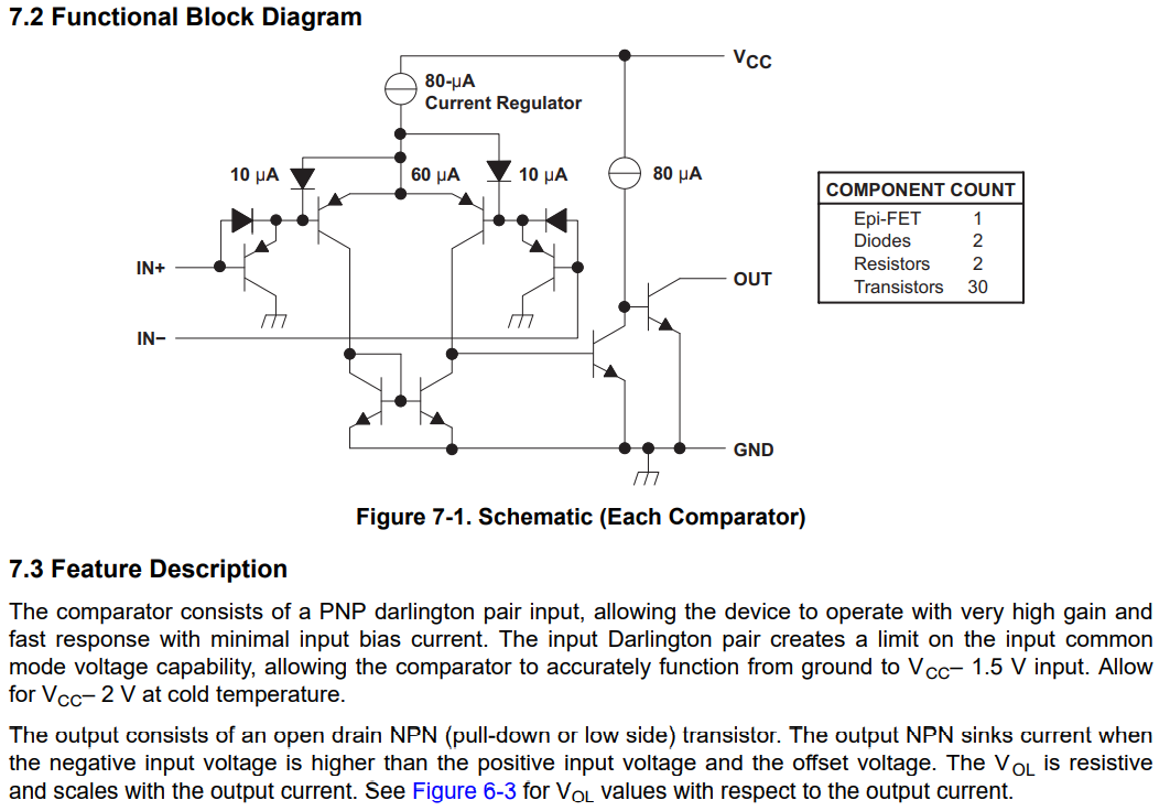
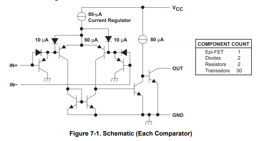
7.3 Feature Description
The comparator consists of a PNP darlington pair input, allowing the device to operate with very high gain and fast response with minimal input bias current. The input Darlington pair creates a limit on the input common mode voltage capability, allowing the comparator to accurately function from ground to VCC– 1.5 V input. Allow for VCC– 2 V at cold temperature. The output consists of an open drain NPN (pull-down or low side) transistor. The output NPN sinks current when the negative input voltage is higher than the positive input voltage and the offset voltage. The VOL is resistive and scales with the output current.
![[Home]](../ipstats.gif)