 robot-electronics display:
 http://www.robot-electronics.co.uk/htm/Lcd02tech.htm
 http://www.robot-electronics.co.uk/htm/Lcd03tech.htm
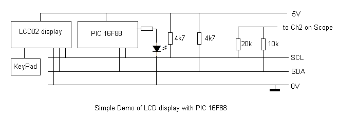
The display uses IIC at address 0xC6.
It is possible to connect a key pad which it scans. This code looks for presses and runs a demo routine on press.
The PIC16F88 uses the IIC master firmware option, so there are firmware routines for START,STOP,RESTART,send and receive and ACK and NACK bits.
 The IIC bus is connected to PORTB pins, and requires 4k7 pull up resistors.
 SCL	EQU	4
 SDA	EQU	1
The code is here:
 http://www.dougrice.plus.com/dev/iic_lcd.ASM
 http://www.dougrice.plus.com/dev/iic_lcd.lst
The 16F88 code draws a line of text and poll the keypad and on key presses it does:
; Displays a line of text: 1234 bbbb xx String
;   bbbb is bit map of keys pressed
;	xx is counter incremented
;	String is written by LCDdispStr and is "Start   ", "Stop   ", or "    "
;
;	Attach keypad to IIC display as described in the web page
;	press keyboard:
;	  key 1 - writes "Start "  at String
;	  key 2 - writes "Stop  "  at String
;	  else  - writes "      "  at String
;
;     key 4 - decrement xx on press and release
;     key 5 - increment xx on press and release
;
;     key 7 - decrement xx on press
;     key 8 - increment xx on press
;
;
;	Blue LED on PORTB,2 lights if LCD display is not connected.
;
The IIC bus uses these primatives at the bit level.
Start:
 SCL ----_____
 SDA --_______

Stop:
 SCL _____----
 SDA _______--

"0"
 SCL __----___
 SDA _________

"1"
 SCL __----___
 SDA _-------_
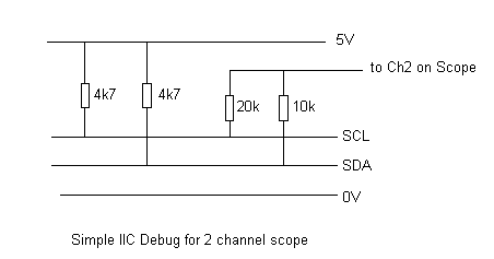
I have used this 2 resistor circuit to debug the code. A 10k and 20 K resistor provide a potential which can be viewed on a scope channel.
Another pin is used as a trigger signal and connected to Ch1. ( Maybe another resistor could be used for the trigger pulse. )
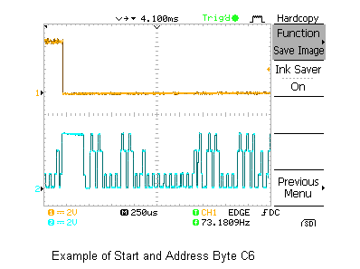
The screen shot below has been annotated to show the START,STOP and "1" and "0" bits.
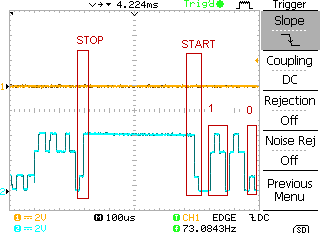
When SCL and SDA are 1 then Blue line is at max
When SCL and SDA are 0 then Blue line is at min
When SDA is 1 and SCL is 0 then Blue line is at 66%
When SDA is 0 and SCL is 1 then Blue line is at 33%
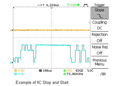
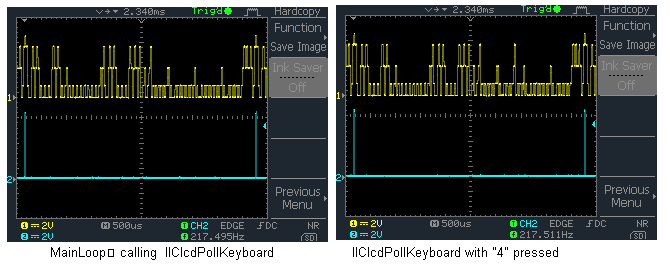
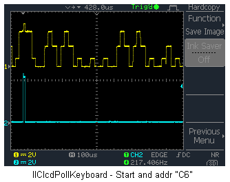
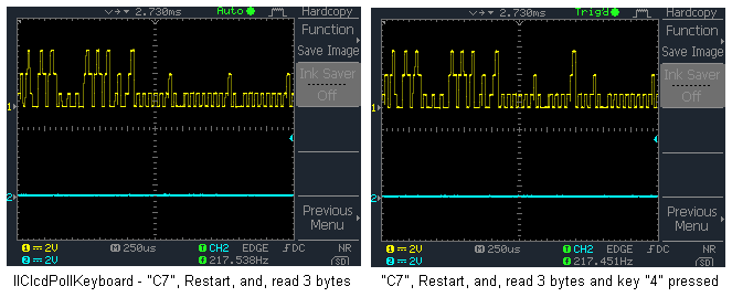
Some more traces, after I added a debug sync pulse, and a 56k resistor to the debug signal:
This code is a simple demo and code be used as a starter for other projects.
Doug Rice, copyright 30/03/2011
![[Home]](../ipstats.gif)