Drive the circuit with a square wave signal and look at the scope.
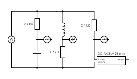
You get the exponential waveforms for the CR circuit and RL .
When looking at the scope trace for the CO-AX signal, it also showed a CR type wave form. Why?
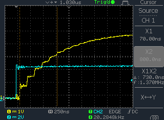
The waveform was on the Hi-Z input of an E1 monitor Amp fed from a 30dB monitor tap.
If you terminated the input with Zo there was not enough signal.
The "time Constant" is "CR" for capacitor resistor CR networks has an equivalent for the Rtap CO-AX circuit.
delta T X steps in Voltage
similar to Numerical Integration
h x gradient
Consider the Gradient of the waveforms at the start and compare the equations that have equal gradients.
The "time Constant" is
TimeConstant = "CR" = ( length of Un terminated Co Ax) / 100 x microseconds x ( Zo + Rtap ) / Zo
"CR" * Zo = Length/speed * ( Zo + Rtap )
So there is no proportial equivalent but I have an understanding!
If Rtap is much greater than Zo it simplifies to
"CR" ~= Length/speed * Rtap/Zo
I did a course at college about using CO-AX to model electronics!
Now you use a digital computer.
Drive a length of cable , 14m of RG58 and we see the steps due to reflections off an open circuit.

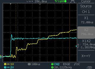
We see Shark Teeth waveforms on the outputs of our video amps. Is this due to CR or the CO-AX reflections?
.png)
.png)
The expected waveforms should be like:
.png)
.png)
This is what the monitor amp waveform looks like, but they work.
No Steps are seen. The Cable lengths we are not seeing steps due to reflections.
.png)
http://www.coax-connectors.com/products/connectors/type-43/43-533-d6-9b-u-link.aspx
http://www.interfacecomponents.com/connectors_TYPE-43.html
The input of the Amp may be a length of cable fed from a 30db CO-AX tap.
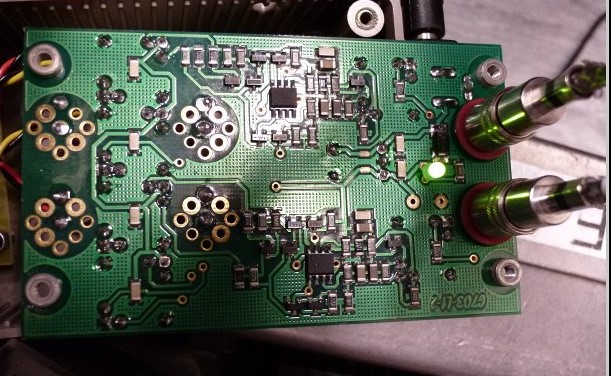

https://pervisell.co.uk/telecomms/index.html
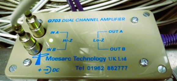
Specification:
Input:

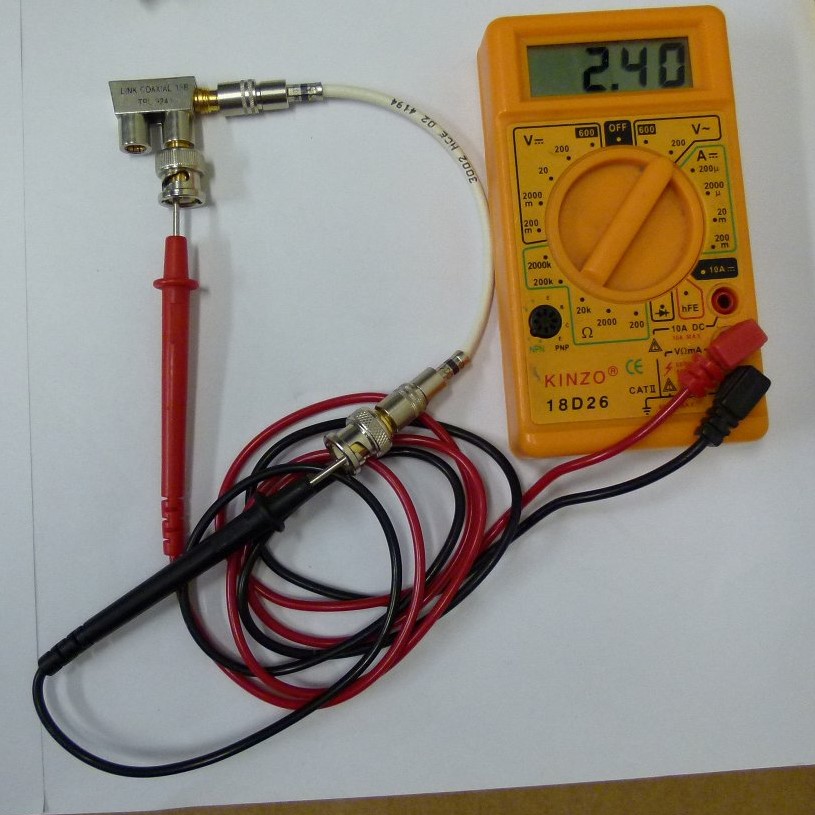
This is a CO-AX link with a 2400 ohm resistor.
 |
 +---[ 2400 ]--- == 75 ohm CO-AX == Hi-Z input
 |
k = 75 / ( 2400 + 75 ) = 0.0303 or 3% increase each reflection.
A CO-AX 1m long would reflect , there and back takes 10ns
So for an E1 488ns __--__ or 244 ns there would be 24 steps.
This is a CO-AX link with a 2400 ohm resistor.
 |
 +---[ 2400 ]--- == 75 ohm == Hi-Z input
 |
k = 75 / ( 2400 + 75 ) = 0.0303 or 3% increase each reflection.
The CO-AX 1m long would reflect , there and back takes 10ns
So for an E1 488ns __--__ or 244 ns there would be 24 steps.
For a 30dB Tap with series resistor:-
Tap: -30.37db 2400.00 ohms loss 30.37db
| step | Vnode/Vout |
| 1 | 0.030303030303030304 |
| 2 | 0.05968778696051423 |
| 3 | 0.08818209644655926 |
| 4 | 0.11581294200878474 |
| 5 | 0.14260648922063976 |
| 6 | 0.16858811075940824 |
| 7 | 0.19378241043336558 |
| 8 | 0.21821324648083937 |
| 9 | 0.24190375416323817 |
| 10 | 0.2648763676734431 |
| 11 | 0.28715284138030844 |
| 12 | 0.30875427042939 |
| 13 | 0.3297011107194085 |
| 14 | 0.3500131982733658 |
| 15 | 0.36970976802265776 |
| 16 | 0.38880947202197114 |
| 17 | 0.4073303971122144 |
| 18 | 0.42529008204820795 |
| 19 | 0.4427055341073532 |
| 20 | 0.4595932451950091 |
| 21 | 0.475969207461827 |
| 22 | 0.4918489284478323 |
| 23 | 0.507247445767595 |
| 24 | 0.522179341350395 |
| 25 | 0.536658755248868 |
| 26 | 0.5506993990292053 |
| 27 | 0.5643145687555929 |
| 28 | 0.577517157581181 |
| 29 | 0.590319667957509 |
| 30 | 0.6027342234739481 |
| 31 | 0.6147725803383739 |
| 32 | 0.6264461385099382 |
| 33 | 0.6377659524944856 |
| 34 | 0.6487427418128345 |
| 35 | 0.6593869011518396 |
| 36 | 0.6697085102078445 |
| 37 | 0.6797173432318492 |
| 38 | 0.6894228782854295 |
| 39 | 0.698834306216174 |
| 40 | 0.7079605393611385 |
| 41 | 0.7168102199865585 |
| 42 | 0.7253917284718143 |
| 43 | 0.7337131912453957 |
| 44 | 0.7417824884803836 |
| 45 | 0.7496072615567357 |
| 46 | 0.7571949202974406 |
| 47 | 0.7645526499853968 |
| 48 | 0.7716874181676576 |
| 49 | 0.7786059812534861 |
For a 10dB Tap with series resistor:-
Tap: -9.99db 162.00 ohms loss 9.99db
| step | Vnode/Vout |
| 1 | 0.31645569620253167 |
| 2 | 0.5327671847460342 |
| 3 | 0.6806256705858967 |
| 4 | 0.7816934963498535 |
| 5 | 0.8507778329480011 |
| 6 | 0.898000037711292 |
| 7 | 0.930278506789997 |
| 8 | 0.9523422704640485 |
| 9 | 0.96742383044378 |
| 10 | 0.9777327448603053 |
| 11 | 0.9847793445880568 |
| 12 | 0.9895960076931022 |
| 13 | 0.9928884103218673 |
| 14 | 0.9951389133845674 |
| 15 | 0.9966772319337549 |
| 16 | 0.9977287408154781 |
| 17 | 0.9984474937219724 |
| 18 | 0.9989387931770445 |
| 19 | 0.9992746181210177 |
It takes 3 steps to get to the 63% T=CR TimeConstant, or 30 ns.
simulated using:-
<script>
var opStr = ""
  // 10 dB Tap
  var Zout = 162
  var k = 75 /( 75 + Zout )
  self.document.write( "|| step  ||  Vnode/Vout  || \n" )
  var Vout=50
  var Vnode=0
  opStr += "0,"
  for( x=1 ; x < 20 ; x++){
    Vnode = ( Vout-Vnode )*k + Vnode
	opStr += Vnode +" , "
	self.document.write( "|| "+ x + " || " + Vnode/Vout + " || \n" )
  }
  // 30 dB Tap
  var Zout = 2400
  var k = 75 /( 75 + Zout )
  self.document.write( "|| step  ||  Vnode/Vout  || \n" )
  var Vout=50
  var Vnode=0
  opStr	+= "0,"
  for( x=1 ; x < 50 ; x++){
    Vnode = ( Vout-Vnode )*k + Vnode
	opStr += Vnode +" , "
	self.document.write( "|| "+ x + " || " + Vnode/Vout + " || \n" )
  }
  //
  // Output driving 8 x -- [ 75 ohm ] --|=== 75 ohm co-ax ===
  //
  self.document.write( "|| step  ||  Vnode/Vout  || \n" )
  var Vout=50
  var Vnode=0
  var Zout = 25
  var k = (75/8)/( 75/8 + 25 )
  opStr	+= "0,"
  for( x=1 ; x < 50 ; x++){
    Vnode = ( Vout-Vnode )*k + Vnode
	opStr += Vnode +" , "
	self.document.write( "|| "+ x + " || " + Vnode/Vout + " || \n" )
  }
</script>
Simulating the Output.
| step | Vnode/Vout |
| 1 | 0.2727272727272727 |
| 2 | 0.47107438016528924 |
| 3 | 0.6153268219383922 |
| 4 | 0.7202376886824671 |
| 5 | 0.796536500859976 |
| 6 | 0.8520265460799825 |
| 7 | 0.8923829426036236 |
| 8 | 0.9217330491662717 |
| 9 | 0.943078581211834 |
| 10 | 0.9586026045176975 |
| 11 | 0.9698928032855981 |
| 12 | 0.9781038569349805 |
| 13 | 0.9840755323163495 |
| 14 | 0.988418568957345 |
| 15 | 0.9915771410598873 |
| 16 | 0.9938742844071907 |
| 17 | 0.9955449341143207 |
| 18 | 0.9967599520831424 |
| 19 | 0.9976436015150126 |
| 20 | 0.998286255647282 |
| 21 | 0.9987536404707505 |
| 22 | 0.9990935567060003 |
| 23 | 0.9993407685134548 |
| 24 | 0.9995205589188763 |
| 25 | 0.9996513155773645 |
| 26 | 0.9997464113289923 |
| 27 | 0.9998155718756309 |
| 28 | 0.9998658704550043 |
| 29 | 0.9999024512400031 |
| 30 | 0.999929055447275 |
| 31 | 0.9999484039616544 |
| 32 | 0.999962475608476 |
| 33 | 0.999972709533437 |
| 34 | 0.9999801523879541 |
| 35 | 0.9999855653730576 |
| 36 | 0.9999895020894963 |
| 37 | 0.9999923651559973 |
| 38 | 0.9999944473861798 |
| 39 | 0.9999959617354035 |
| 40 | 0.9999970630802935 |
| 41 | 0.9999978640583953 |
| 42 | 0.9999984465879238 |
| 43 | 0.9999988702457628 |
| 44 | 0.9999991783605547 |
| 45 | 0.9999994024440398 |
| 46 | 0.9999995654138472 |
| 47 | 0.9999996839373434 |
| 48 | 0.9999997701362497 |
| 49 | 0.9999998328263634 |
Another type of E1 "video" monitor amp drives 8 x 75 ohm cables. The signal has a pronounced Shark tooth shape.
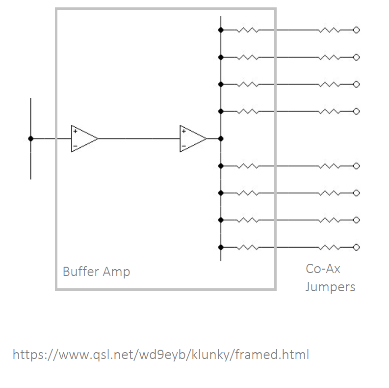
The output is probably designed to drive a circuit:
Amp ---[ 75 ohm ] ---===75ohm coax === | === 75Ohm coax === | -- [75 ohm load ]--
In reality the Amps are driving 8 lengths of un terminated 75 Ohm cable
   Amp,Vout --[ Zout ] --+---=== 75ohm coax === | O/C
                         |
                         +---=== 75ohm coax === | O/C
                         |
                         +---=== 75ohm coax === | O/C
			 |
		         +- Vnode
So while the signal is traveling down the 75 ohm coax, it is 75 Ohm resistor.
When the signal bounces off the O/C and back, it is then High Z.
The 75 ohm resitor between the Amp and Co-ax absorbs the reflection. It is assumed that the Amp output is low impeadance.
In this case, We are not seeing steps, only the Sharks Teeth.
So we can itterate:
Vnode = Vout * K
where K is [ Zout ] / (Zout + Zco-ax/8)
When the signal bounces back for the next T bounce.
Vnode = (Vout-Vnode)*k +Vnode
The speed of signal is 200m / microsecond, but as it got there and back 100m /micro second.
Tbounce = length /100 microseconds.
A cable 10m long Tbounce is about 100 ns
Itterate this and you will get a CR type curve.
What is the Time constant?
For a CR network the t= CR and is when V gets to about 0.63 or = ( 1 - exp( -1 ) )
So when does the way for get to 0.63 of max. It will need more iterations the smaller K, and will be proportional to t.
If we itterate for k = 0.1 you need about 8 itterattions before Vnode gets to 63%
What is a typical Zout? 75 ohm. K = 0.11
It takes about 8 itterations to get to 63 % or the "TimeConstant"
So for a 10 metre cable it takes 8 * 100ns or 800ns.
 __---___   ___---___
         ---
</div>
<script>
  var Vout=10
  var Vnode=0
  var Zout = 25
  var k = (75/8)/( 75/8 + 25 )
  var opStr= "0,"
  self.document.write( "\n" )
  for( x=0 ; x<20 ; x++){
    Vnode = ( Vout-Vnode )*k + Vnode
	opStr += Vnode +" , "
	self.document.write( x+ " , " + Vnode/Vout +"\n" )
  }
  self.document.write( "\n" )
</script>
I plotted this calculation.
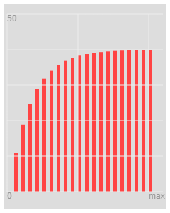
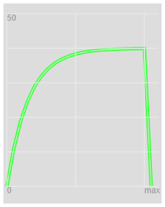
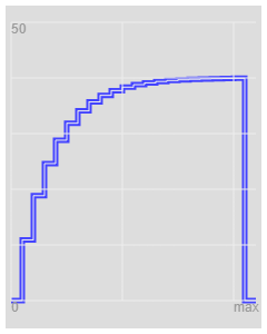
For a resistor Capacitor
 - - [   ] - - - |   | - -
       R           C
The Time Constant is R x C
V = I R
dV/dT = I C
So the Gradient of increase in voltage is 1 when CR == 1
So for the CO-AX
the Gradient = step / delta T
where step is
Zo / ( Zo + Rtap ) = K
The number of Steps need is 1 / K
Steps = ( Zo + Rtap ) / Zo
And delta T is
Length / speed
For CO-AX there and back
deltaT = length / 100 metres per micro second
The "time Constant" is CR and equivalent
delta T X steps
The "time Constant" is
TimeConstant = "CR" = ( length of Un terminated Co Ax) / 100 x microseconds x ( Zo + Rtap ) / Zo
"CR" * Zo = Length/speed * ( Zo + Rtap )
So there is no proportial equivalent but I have an understanding!
Switched capacitor filters emulate resistance using capacitors.
R = C x T
You let current flow into a capacitor for a proportion of time
https://pervisell.co.uk/telecomms/index.html

Thévenin's theorem and its dual, Norton's theorem, are widely used to make circuit analysis simpler and to study a circuit's initial-condition and steady-state response.
Thévenin's theorem - voltage - zero impedance in series
Norton's theorem - Current - high impedance in parallel.
The generator is low impedance.
The voltage across the Generator is V if it's own and 0 if its from the far end.
Unterminated 30m ? cable :
Terminated 30m ? cable :
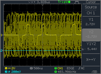
reflections 11m ? cable :
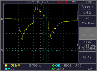

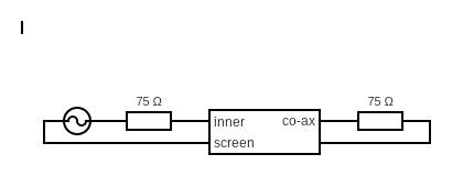
Below, the resistor on the left terminates reflections from the far end. You could use this to measure the output impedance of the oscillator.

What an E1 2048 Bps G.703 signal should look like, when correctly terminated:
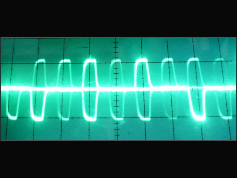
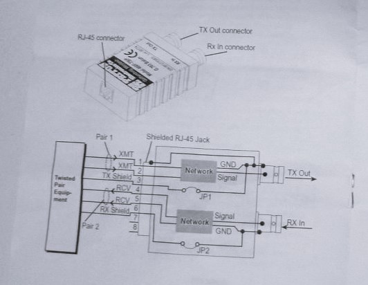
What a G.703 signal into a long 120ohm Balanced CAT 5 cable unterminated. The pulses are 488ns wide. In cable the speed is about 2/3 speed of light. For a 100m cable, the there and back is delay about a microsecond. This make my CAT5 cable about 50m long.
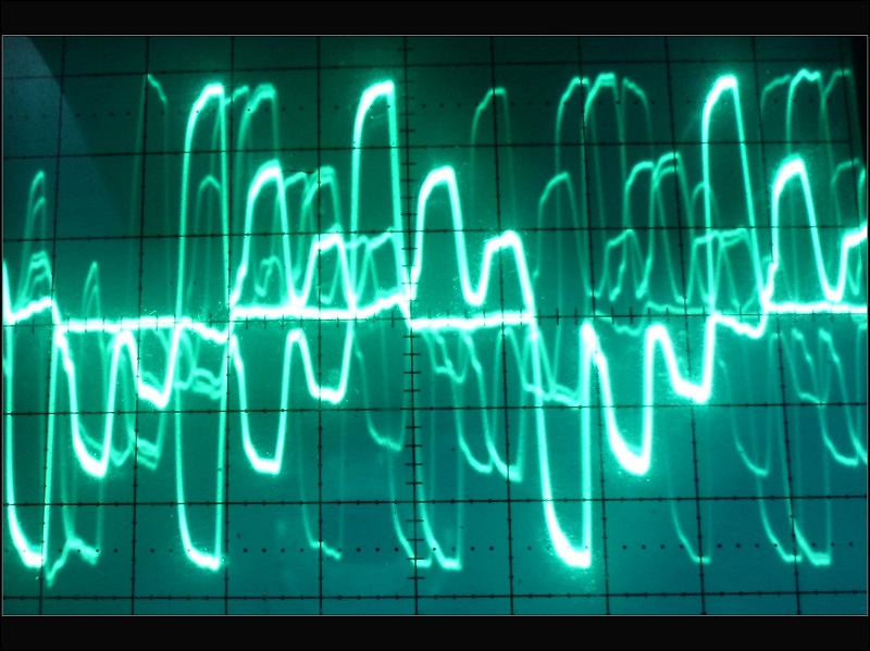
A 75 ohm Co-Ax cable is like a 75ohm resistor, while the pulse has not go to the far end and back. The picture below shows this.
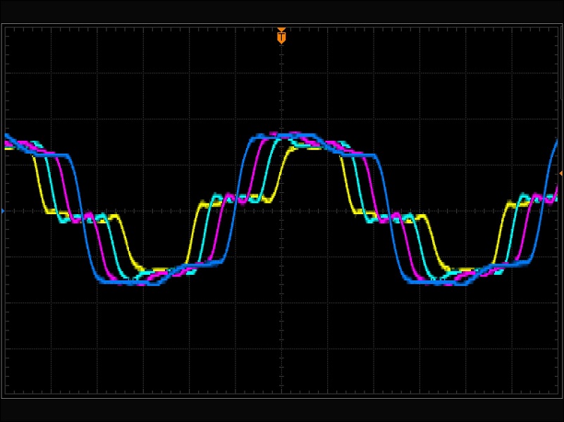
A square wave feeding a coax monitored by a 4 channel scope with 1m of cable between each input.
I think the blue trace is at the far end, Magenta 1m back from end, Cyan 2m back from end, Yellow 3m from end and 1m to the square oscillator. The frequency is adjusted to suit.
 [ OSC ] --[1m]--|--[1m]--|--[1m]--|--[1m]--|
                ch1      ch2      ch3      ch4
              yellow     cyan    magenta  blue
