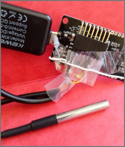
These nodeMCU with display are logging temperatures
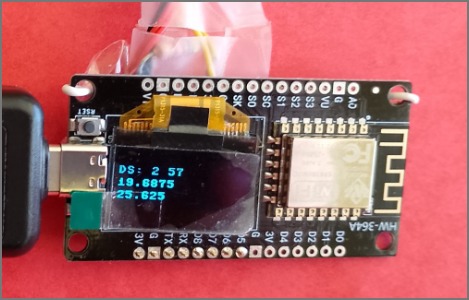
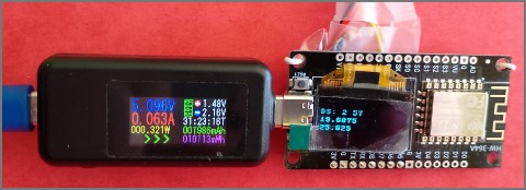
They are using about 60mA.
eBay suggested the ESP01 and these modules using the ESP8226.
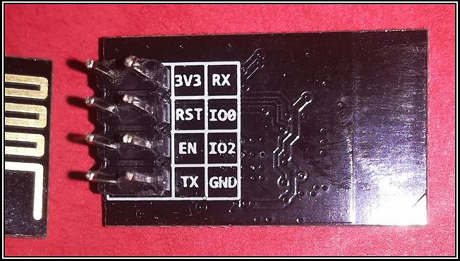
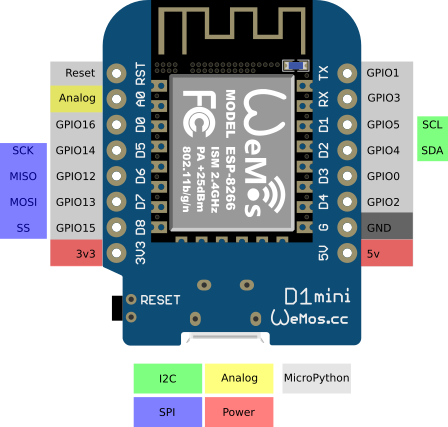 and
and 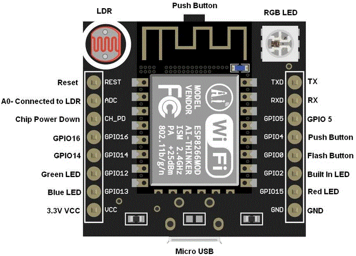
These were very reasonably priced and the ESP8226 chip has a later version more suited to HTTPS.
see https://www.schatenseite.de/en/2016/04/22/esp8266-witty-cloud-module/
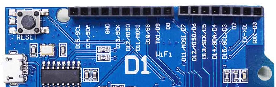
https://randomnerdtutorials.com/esp8266-pinout-reference-gpios/ - Useful Guides
https://thonny.org/ provides a way to use Python and can flash these modules, by selecting the interpreter.
NOTE: I found I had to specify the size of the serial ROM to 4MB , Otherwise the little blue light flashed really fast and the REPL
Thorny comes with the Raspberry Pi.
I brought some boards with an ssd1306 soldered on and it need this:-
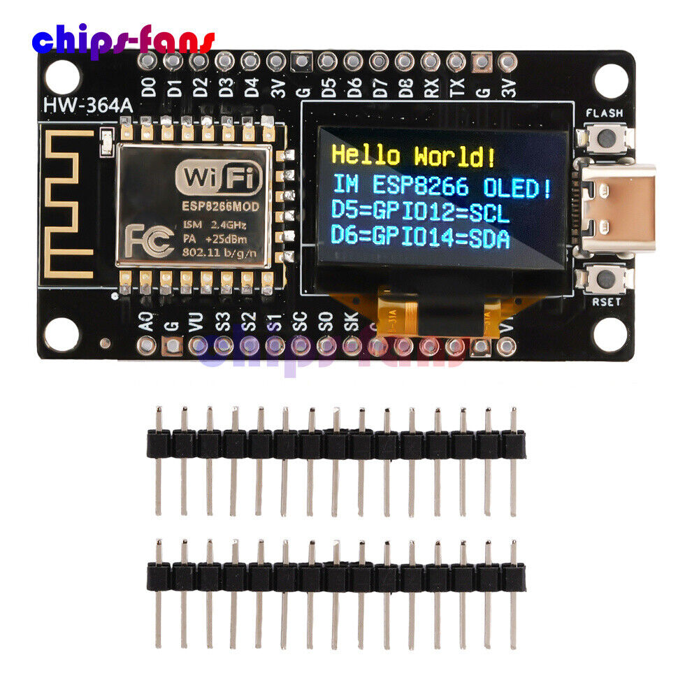
 from machine import Pin, I2C
 import ssd1306
 # using default address 0x3C
 #i2c = I2C(sda=Pin(5), scl=Pin(6))
 #
 # Hello World!
 # IM ESP8226 OLED!
 # D5=GPIO12=SCL   !!- typo?
 # D6=GPIO14=SDA   !!- typo?
 #
 # This works for my modules:-
 # i2c = I2C(sda=Pin(14), scl=Pin(12))
display = ssd1306.SSD1306_I2C(128, 64, i2c)
This worked -( needs Shift-Tab to sort out indentation ) :-
 from machine import Pin, I2C
 import ssd1306
 # using default address 0x3C
 #i2c = I2C(sda=Pin(5), scl=Pin(6))
 #
 # Hello World!
 # IM ESP8226 OLED!
 # D5=GPIO12=SCL   !!- typo?
 # D6=GPIO14=SDA   !!- typo?
 #
 # This works for my modules:-
#i2c = I2C(scl=Pin(5), sda=Pin(4), freq=100000)
 i2c = I2C(sda=Pin(14), scl=Pin(12))
 display = ssd1306.SSD1306_I2C(128, 64, i2c)
 #The text seems to be added
 display.fill(0)
 display.text('Hello World', 0, 0, 1)
 display.text('Hello Doug', 0, 8, 1)
 display.text('Hello ', 0, 16, 1)
 display.show()
 #count and display
 count = 0
 while True :
   count +=1
   #fill(0) erases screen and is needed
   display.fill(0)
   display.text( str( count ) , 0, 16, 1)
   display.show()
The Arduino IDE can be used. It has loads of useful examples to learn about simple IOT using HTTP and other protocols.
http://www.ulisp.com/ can be uploaded.
I recently looked at the website, and it does not list the 8226 in the devices.
I remembered I had tried it on an ESP-01, so this is what I found.
http://forum.ulisp.com/t/is-anyone-still-using-the-esp8266/1432 askes if anybody is still using it.
The last version for 8226 found in Older Releases which has "#if defined (ESP8266)"
ESP Release 4.4d - 30th June 2023
 uLisp ESP Release 4.4d - www.ulisp.com
   David Johnson-Davies - www.technoblogy.com - 30th June 2023
Licensed under the MIT license: https://opensource.org/licenses/MIT
 #if defined (ESP8266)
  #include <ESP8266WiFi?.h>
 #elif defined (ESP32)
  #include <WiFi?.h>
 #endif
I copied the text into a new sketch for the Arduino IDE and compiled and uploaded it to an ESP-01.
I had used the Arduino IDE Version: 2.3.7 to upload the blink sketch to the ESP-01. It has board ESP8266 ver 3.1.2 installed
http://www.ulisp.com/show?1AA0
Versions after 4.4d do not have #if defined (ESP8266)
 uLisp ESP Release 4.9a - www.ulisp.com
   David Johnson-Davies - www.technoblogy.com - 2nd March 2026
https://protosupplies.com/product/esp8266-witty-cloud-esp-12f-wifi-module/
https://yoursunny.com/t/2016/WittyCloud-first/ - interesting little module.
https://jpralves.net/post/2016/11/15/esp8266.html - loads of useful information
https://github.com/tasmota/docs/blob/master/docs/devices/Wemos-D1-R1-%26-R2.md - looks intersting
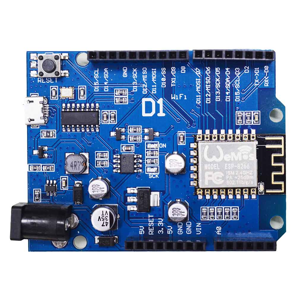
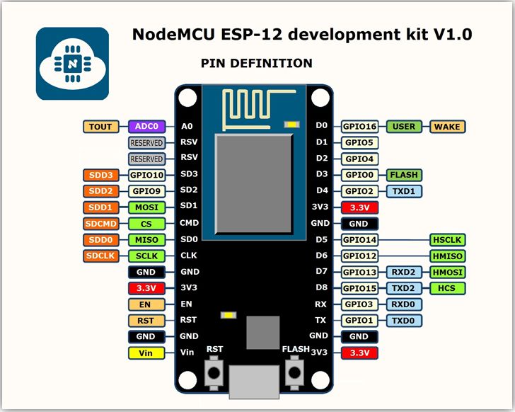
My nodemcu module can overload the USB socket, and the serial chip has no part number.
I brought some boards with an ssd1306 soldered on and it need this:-
The 12 LED ring connected to GPIO2 turns on bright, when the device is rebooted.
When the ESP-01 boots, it seems that the UART1 TX is connected to the GPIO2 pin and causes issues.
"... When the ESP8266 goes into serial bootloader mode, the Boot ROM switches GPIO2 to an output and the UART TX signal is also output to this pin. For this reason GPIO2 should not be directly connected to VCC. Similarly, make sure GPIO2 is not connected to another peripheral where this may cause an issue when in download mode. ..."