Some Thoughts.
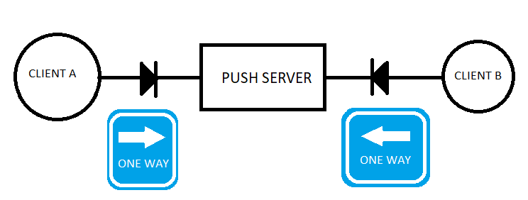
I have worked on signalling setting up telephone calls.
This diagram is a summary.
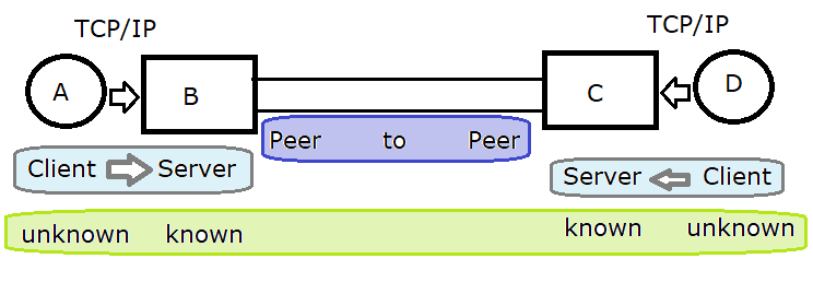
Consider a Telephone call.
[ user A ] [ Telephone ] [ network ] [ Telephone ] [ user B ]
We all know how a phone call works, but probably do not agree, if we worked together to write it down.
[ User A ] dials [ User Bs ] number and it is answered so User A can talk to User B and User B can talk back.
User A dials B and is guided by tones
User A picks up phone to make a call to User B
	They expect to hear dial tone before they start to dial
	They expect to hear Ringing or a network announcement
	When User B answers, User B says hello and both
	User A confirms they are talking to User B
	User B confirms they are talking to User A
Consider two users making calls over modems [ UserA ] - [ A ] [ B ] [ UserB ]
Consider the two modems [ UserA ] - [ A ] [ B ] [ UserB ]
Conventionally, the modems are used over an answered call. Then the Modems have to align end to end.
What do I mean by align?
C7 User parts like ISUP use MTP. MTP level2 signalling links align. They are out of service , in service and other states. See ITU Q.702, Q7.3, Q704
In a C7 Signalling link, the exchange assumes they are between two known endpoints over known wiring.
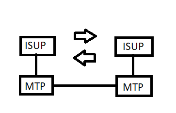
C7 users User parts,
ISUP ISDN user Part is used to signal call states. MTP the message transfer part. ITU Q.702, Q.703 and Q.704 SLT - Signalling Link Test Messages - configuration and wiring check. ITU Q.707
ISUP is written such that it copes if the MTP is not available at the start, middle and end of the call.
MTP manages many signalling between known points. A signalling link has a state machine at both ends and has these 2 states and others:
The state machines are controlled by primitives. A primitive is a message or command that has a locally defined API.
Via management commands, the signalling links are brought into service, and try an align, and report when in service
In C7 signalling, after the links have been brought into service, the wiring configuration is checked by the use of SLTM, which get an SLTA, if the other end agrees.
C7 MTP sends messages in packets that start with a FLAG 01111110 and end with CRC followed by a FLAG. Any 01111110 inside the message are escaped, so they are not considered to be a flag. The CRC code is used to check for transmission errors. Messages that have errors cannot be trusted and are discarded.
Two users want to talk to each other using TTY terminals. Codes like ASCII have a set of letters, numbers, punctuation and control codes.
Characters are sent back and forth.
Consider two users:-
User A makes a call to User B
When can User A start typing?
When can User B start typing?
What happens when the user types, but it cannot be sent to User B cannot type?
What happens when the user types, it can be sent, but User A does not think it can be received by User B?
What does the system do to text typed by the user, when [ User A ] X-- [ User B ]
What does the system do to text typed by the user, when [ User A ] --- [ User B ]
The flow control is really done by the users observation of the conversation.
A user would expect a small amount of silence , until some text indicating the call has been answered.
The user would probably type some message to initiate conversation, after a period of silence.
The Textphones have very limited display used by both ends, so the conversation has to have some protocol so users type in turn.
The RelayUK App can tolerate some over typing, when both ends type at the same time.
At the end of the phrase, the user types GA
At the end of the call SK can be sent to say Stop Keying.
The Textphone manuals list these.
The history of Textphones is such there are a number of protocols used in the V.18 spec.
V.18 Sends CI before the Modem ANS is received
V.21 4 wire, 4 frequency DUPLEX, both ends can type at the same time, but the display may require uses type in turn.
BAUDOT SIMPLEX users have to type in turn
EDT - SIMPLEX users have to type in turn
DTMF Do not use and IVR also
BELL103 like V21 but diffent frequencies
RelayUK App + Call The user can type and speak and read and hear at the same time, if using headphones and device in front of them
Typically the Modem takes a serial signal, using voltages encoding the "1"'s and "0" using MARK and SPACE and uses FSK frequency Shift keying.
[computer program]--[UART]--[modem]--[telephone system]--[modem]--[UART]--[computer rogram]
Very useful diagrams from https://docs.rs-online.com/a02c/0900766b800af005.pdf - data sheet for V21 modem.
It is quite simple to analyse the samples exported from Audacity using JavaScript, using code run for each sample.
The samples are passed into IIR filters to detect the V.21 FSK signals.
Some logic is needed to decide if the FSK is encoding a "1" or "0".
Logic is used to find the "1"'s MARK and "0"'s SPACE. These are fed into the UART. It looks for the start bit and then clocks 5 bits for BAUDOT or 8 bits for V.21.

https://www.dougrice.co.uk/cgi-bin/wiki.pl?WebAudio
This datasheet has a nice colour image.
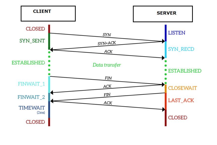
https://dev.to/tamerlang/tcp-in-depth-3g83
NOTE: Both ends of TCP must close their end of the connection.
https://www.geeksforgeeks.org/tcp-connection-termination/
Graceful Connection Release : The common way of terminating a TCP connection is by using the TCP headers FIN flag. This mechanism allows each host to release its own side of the connection individually.
Both ends need to call close().
For C7 ISUP, a REL releases the circuit from either end, and waits for a RCL.
The TCP API does not seem to have a call back function to report the FIN.
The functions block
  socket()
  bind()
  listen()
  accept()
  read()
  write()
  close()
  socket()
  connect()
  write()
  read()
  close()
It the text does not arrive, You may need to call flush(), and disable waiting for end of line, or close the connection.
My background is the C7 Event driven model using SDL. We wrote the code to go in the event handler, and somebody else provided the framework.

and
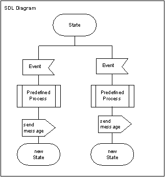
This requires a programming model like the interrupt vectors on a micro controller. Also a Sleep that can be woken by the interrupt as in a PIC16F series chip.
http://www.dougrice.plus.com/hp/Theory/Index.htm has thoughts about this.
I think the TCP API is for the command line pipe flow like:-
dir * | more | more | more | more | more | more | more | more | more | more
ISUP messages manage a circuit identified by OPC,DPC,CIC SLS is used to route messages over the same signalling links.
  IAM ->
  <- REL
  RCL ->
  IAM ->
  <- ACM
  <- ANS
  REL->
  <-REL
REL-
http://ccgi.dougrice.plus.com/cgi-bin/wiki.pl?Wet_String_Theory
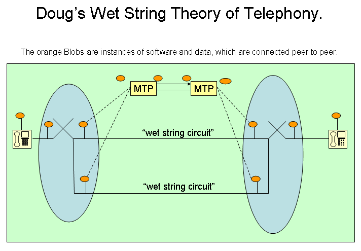
When I had my first PC about the the time of the IBM PC, we used serial ports and RS232 leads. I did not have a dial-up modem. The RS232 leads could be tricky to get to work. I had a Ball Point Pen test, short pin 2 and pin 3 and see if you got echo.
At the time, I never really understood RTD,DTR,RTS,CTS in the modem context and an RS-232 lead does not have the CD.
People used to have a box to fake the signals to get RS-232 leads to work, and there are various null-modem wiring diagrams.
If you played with the UART on the IBM-XT, the modem signals could be used and were used for inputs and people used them to program MicroChip microcontrollers like the PIC16F84. See:- http://www.dougrice.plus.com/btinternet/picprog/mypic.htm
This website has some clear words:-
https://pinoutdiagrams.com/rs232/rs232-pinout
Serial interfaces use a specific arrangement of wires and connectors to facilitate communication between devices. Each connector has a designated role, ensuring that signals are transmitted and received correctly. Heres a breakdown of the typical configuration:
These contact points are critical for establishing and maintaining robust communication between devices.
https://www.virtual-serial-port.org/article/what-is-serial-port/rs232-pinout/ could be interesting.
If you are receiving a CD signal, you can transmit text on behalf of the User,
If you are not receiving CD, you can send short bursts of characters to probe.
It the burst is too long, then the remote end may get the CD raised and assume it is safe to send User's Text.
When using just the TX and RX on a PIC micro-controller, I suppose you could send periodically and if you get a reply, trigger a timer to simulate a CD signal.