Modems are used to connect a terminal to a remote computer, over a telephone connection. This connection may need establishing and could be dropped before the user hangs up.
Typically the Modem takes a serial signal, using voltages encoding the "1"'s and "0" using MARK and SPACE and uses FSK frequency Shift keying.
[computer: [computer program]--[API]--[UART]--]--[RS232 cable]--[ DB25 connector ]--[modem]--[telephone system]--[modem]--[UART]--[computer program]
Over the passage of time, the functionality has moved around the powered boxes, which are connected by wires and connectors that may have become disconnected, breaking the end to end connection.
my unknown theorem - Notes on
The early history of BAUDOT - The early history of BAUDOT from the 1870's is really interesting, as Time Division Multiplexing was used to share a telegraph wire.
By the time the Client A user starts typing to Client B, it is between "known" to "known" end points. Before you log in, or set up the telephone call, it is between "unknown" to "known" endpoints.
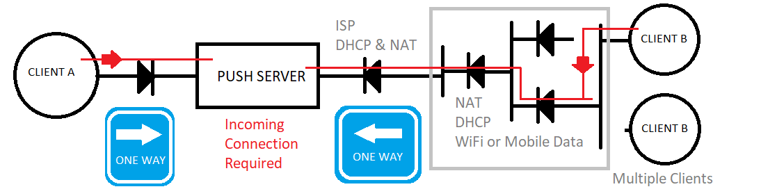
A server cannot initiate the connection to the client. So the Client Server protocols are typically request - respond. I could call this Doug Rice's "Unknown" theorem.
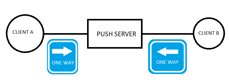
This diagram is important to me.
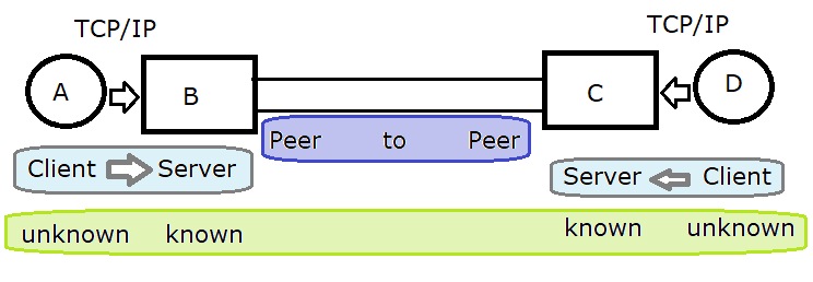
If A connects to B so B "knows" how to get back to A, and D connects to C. A can connect to C, to get to D
Consider the protocols over different time frames.
If you consider the protocol over the next microseconds, milli seconds, seconds, tens of seconds, classify if it is Client Server or Peer to Peer?
Also consider the spacial / geographic distant. UK PSTN Telephony used STD or Area codes.
| endpoint A | endpoint B | endpoint C | endpoint D |
| unknown | known | known | unknown |
Unknown to known must be Client Server
Peer to Peer need "known" to "known"
By the time the user starts typing, it is between "known" to "known" end points.
Before you log in, or set up the telephone call, it is between "unknown" to "known" endpoints.
For a Telephone conversation:
For VoIP using IP4:
The early history of BAUDOT from the 1870's is really interesting, as Time Division Multiplexing was used to share a telegraph wire.
http://www.computer-timeline.com/timeline/emile-baudot/ has some background.
https://www.rtty.com/England/fiveunits.htm and https://en.wikipedia.org/wiki/Time-division_multiplexing.
Sam Hallis has this: http://www.samhallas.co.uk/repository/telegraph/b6_baudot_multiplex.pdf -
http://www.samhallas.co.uk/telhist1/telehist2.htm - worth a read
Enough of that!
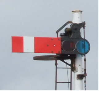
Starting a web page about modems with pictures from railway signalling may seem odd, but there is an analogy.
A user of a computer terminal connecting to a remote computer wants their typing to reach the remote computer, so there is a need for signalling between the terminal, and modems and remote computer.
The user wants to be happy that their typing is going to get to the far end and remote computer. It goes via many cables and boxes. The cables may be come disconnected and the modem boxes need to be powered up.
This signal allows the signal box communicate with the train. When it is horizontal, the train has to stop.
RS-232 has signals like: DTR , DSR and RTS and CTS.
The signal man uses the signal box levers to set the signals using rods and wires.
This picture of the block instrument allows the signal box ahead to report if the line ahead is blocked, clear, or "Train on Line"

A user of the terminal wants to know if the connection is "blocked", or "clear to type" or if typing has arrived at the computer.
[computer: [computer program]--[API]--[UART]--]--[RS232 cable]--[ DB25 connector ]--[modem]--[telephone system]--[modem]--[UART]--[computer program]
A user of the terminal is like the train driver, they want to hold back their typing until the connection is ready to accept their typing.
They may want to hold back their typing, if their typing is backing up. - "train on Line"
This page has notes about modems, RS232, and Programming API. I am trying to understand the names and meanings of the signals in an RS-232 cable. I first used RS-232 cables to connect early IBM PCs to printers, using DB9 and DB25 male and female plugs.
There are many abbreviations: DTE, DCE, DTR, DSR, RTS, CTS, RI, DCD, Circuit 1XX, ITU V.24, V.25, V.18, RS-232, DB9, DB25 , male, female, crossover and many more.
The RS-232 and V.24 cable has signals that have names that date back to the early 1960's.
These names persist into the API, and this page attempts to document this and remember their original meanings.
A terminal was plugged into a modem/"dataSet" that was connected to the private wire / telephone line which routed to a remote modem connected to a computer. This was before micro processors, so signals were carried on one wire per signal. Later on, time division multiplexing -TDM could encode signals as a bit in a serial frame.
ITU V.25:
This document has a very useful summary.
See the Cable and Adapters diagrams. The Minimum Straight Cable diagram explains how the signals are grouped.

So:-
Over the years, more functionality has been added to the DCE / modem. The ITU V.24 tries to accommodate this, making it difficult understand.
Early Terminals were electro mechanical with lots of metal and solenoids and relays. Names like Creed , Teletype KSR33 come to mind. The online videos are worth watching.
This website is excellent, and has some well drawn diagrams:-
https://www.cryptomuseum.com/telex/index.htm - "Classic configurations" section has wiring.
https://www.cryptomuseum.com/telex/svg/tty_2w_1c.svg example circuit.
The 20ma current loop seems the natural way to connect a key in one box to a solenoid in another box.
Early Terminals and Teletypes had a 20mA interface and possibly used private wires, but a need to connect long distances over the telephone network needed modems.

The 20mA loop interface was augmented by the RS-232 and V.24 interface.
In 1958, BELL sold a modem that worked with the Teletype using BELL101. See:- https://en.wikipedia.org/wiki/Bell_101
The modem converted the serial to modem tones that could be used over a telphone connection.
Early modems used acoustic couplers as phones were hard wired in and in the UK you rented the phone off the GPO.
Dialling the call was done on the phone, and the handset was put on the Acoustic coupler.
The modem was connected to the computer using a RS232 or ITU V.24 cable. This is why these cables have the signals they have. The names are of their time, but the usage has changed over the years.
https://www.historyofinformation.com/detail.php?id=765

Popular Electronics published this:-
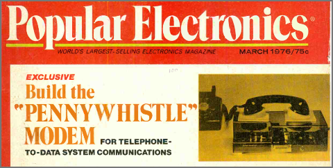
The circuit is:
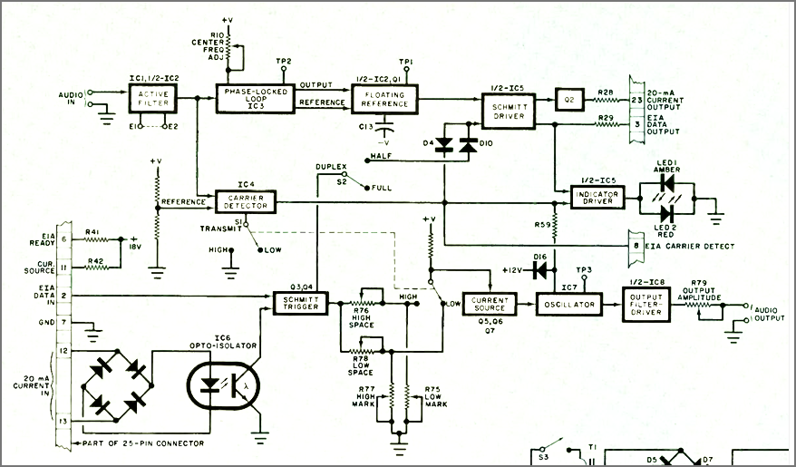
The Penny Whistle modem used RS-232 and the signals on RS-232 are best understood from here.
The incoming tones were decoded using a Phase lock loop chip like an NE565 PLL chip.
Typically the Modem takes a serial signal, using voltages encoding the "1"'s and "0" using MARK and SPACE and uses FSK frequency Shift keying.
[computer: [computer program]--[API]--[UART]--]--[RS232 cable]--[ DB25 connector ]--[modem]--[telephone system]--[modem]--[UART]--[computer program]
or:-
[computer program]--[USB modem: --[UART]--[modem]--]--[telephone system]--[modem]--[UART]--[computer program]
These are very useful diagrams from https://docs.rs-online.com/a02c/0900766b800af005.pdf - data sheet for V21 modem.


Later on Modems had a serial interface on the computer side and listened for the Hayes AT commands.
Another serial interface was connected to the modem connected to the telephone line via an RJ11 connector.
The wiring of the cable from the modem sometimes uses the Phone - 4 wire convention and sometimes the Modem 2 wire convention.
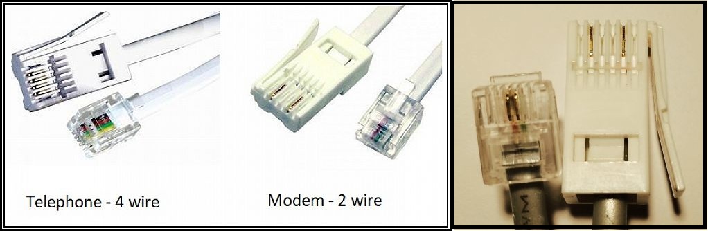
The US connectors used different wiring to the UK conectors. Some UK modems use the US wiring and some use the UK wiring.
This is very detailed:-
https://www.cryptomuseum.com/phone/index.htm - Wiring standards
RS-232 is very much alive, but more at the API interface than the DB25 cable.
Many microcontrollers use the USB-CDC that is used by USB serial port devices, so they can use the API.
https://en.wikipedia.org/wiki/USB#Device_classes | https://en.wikipedia.org/wiki/USB_communications_device_class
ITU V.24 defines the circuits. The diagrams below are useful summaries.
This document has a very useful summary.
See the Cable and Adapters diagrams. The Minimum Straigt Cable diagram explains how the signals are grouped.
The ITU V.24 spec also explains this in words. This diagram is helpful.

Normal timing sequences during establishment of communications are shown below.
On half duplex circuits, RTS is dropped as soon as the data is sent. This is to signal a turn around of the circuit.
 DTR > _ _ - - - - - - - - - - - - - -
 DSR < _ _ _ - - - - - - - - - - - - -
 RTS > _ _ _ _ - - - - - - - - _ _ _ _
 CTS < _ _ _ _ _ - - - - - - - - _ _ _
TD > _ _ _ _ _ _ - - - - _ _ _ _ _ _
CD < from modem indicating Carrier is being received.
So we can apprecate that DTR and DSR can be used to check if the modem connectected to the terminal is plugged in and powered up.
RTS and CTS: "Request to Send" and "Clear to Send" can be used to start typing.
These signals now days have many new usages.
I have used the modem control pins like DTR and RTS as outputs and the CTS for inputs for programming Pic Chips like the PIC16F84.
http://www.dougrice.plus.com/btinternet/picprog/mypic.htm - Many people used the serial port to program the PIC16F84 microcontroller.
http://www.dougrice.plus.com/hp/picprog/ - using Delphi
On PCs using DOS it was easy to access the UART direct. You could set and poll the modem pins. Later on you had to use an API.
Here are some.
It was possible to access the UART chip registers.
https://en.wikipedia.org/wiki/8250_UART
or
https://en.wikipedia.org/wiki/16550_UART
https://web.archive.org/web/20180826215135/http://www.ti.com/lit/ds/symlink/pc16550d.pdf - Datasheet
You can send the output of one command to the serial port.
C:\Users\dough>dir >> com3:
use the mode command to list available com ports
mode
 C:\Users\dough>help mode
 Configures system devices.
 Serial port:       MODE COMm[:] [BAUD=b] [PARITY=p] [DATA=d] [STOP=s]
                                [to=on|off] [xon=on|off] [odsr=on|off]
                                [octs=on|off] [dtr=on|off|hs]
                                [rts=on|off|hs|tg] [idsr=on|off]
Device Status: MODE [device] [/STATUS]
Redirect printing: MODE LPTn[:]=COMm[:]
Select code page: MODE CON[:] CP SELECT=yyy
Code page status: MODE CON[:] CP [/STATUS]
Display mode: MODE CON[:] [COLS=c] [LINES=n]
Typematic rate: MODE CON[:] [RATE=r DELAY=d]
C:\Users\dough>
C:\Users\dough>mode com3 baud=300 parity=n data=8 stop=2
Status for device COM3:
    Baud:            300
    Parity:          None
    Data Bits:       8
    Stop Bits:       2
    Timeout:         OFF
    XON/XOFF:        ON
    CTS handshaking: OFF
    DSR handshaking: OFF
    DSR sensitivity: OFF
    DTR circuit:     ON
    RTS circuit:     ON
C:\Users\dough>dir >> com3:
If the com port number is greater than COM9: you can use "\\.\com13"
You could rename the comport to be withing the COM1: to COM9:
If the name of the port is \\.\COM10, the correct way to specify the serial port in a call to CreateFile() is as follows:
CreateFile( "\\\\.\\COM10", // address of name of the communications device
On linux there is stty. There is a lot of API.
You can send the output of one command to the serial port.
C:\Users\dough>dir >> com3:
The "curse of the command line" makes it simmple to pipe one command to another. These pipes are from left to right and block.
It is not simple to have a list of commands that allow both way typing like two Putty Terminal sessions connected back to back.
The getchar() blocks.
You have to put the getchar() in a thread and it can set a flag if there is text available.
http://www.dougrice.plus.com/dev/serial/test.c
You need to use a thread for keyboard input and sends commands to a modem using the Hayses AT commands.
https://github.com/doug-h-rice/virtual-multicomp is a project to simulate a Z80 and 6809 and uses a tread for the keyboard.
getchar() blocks, preventing other functionality from being processed. I considered this on this web page.
http://ccgi.dougrice.plus.com/cgi-bin/wiki.pl?Wet_String_Theory
JavaScript now has Await and Promises.
I have used Fabrice Bellard's Tiny C on the Windows.
https://learn.microsoft.com/en-us/windows/win32/devio/configuring-a-communications-resource
LUA: https://github.com/ynezz/librs232/blob/master/src/rs232_windows.c
http://en.wikibooks.org/wiki/Serial_Programming/termios - linux
https://developer.chrome.com/docs/capabilities/serial - WebAPI serial with examples
https://developer.mozilla.org/en-US/docs/Web/API/Web_Serial_API - - WebAPI serial without examples
Using Web_serial to do RS232 to a Modem.
https://developer.mozilla.org/en-US/docs/Web/API/Web_Serial_API
https://developer.mozilla.org/en-US/docs/Web/JavaScript/Reference/Statements/async_function
https://developer.mozilla.org/en-US/docs/Web/JavaScript/Reference/Global_Objects/Promise
https://javascript.info/async-await
http://ccgi.dougrice.plus.com/cgi-bin/wiki.pl?AT_Commands_-_Serial_Using_Web_Browser
Doing a view-source on this is enlightening:-
https://homepages.plus.net/dougrice./dev/DigiSpark/simpleterm/simpleterm.html
It has a call back function that is used to deliver text.
function handleIncomingText(text)
https://codezup.com/javascript-promises-async-await-guide/
https://docs.arduino.cc/language-reference/en/functions/communication/serial/available/
When using microcontrollers like the Arduinio, the API can poll to see if there are characters awaiting.
On the other API, it is difficult to find a command that says how many characters are available, and the API can block awaiting a character.
I call it "the curse of the command line".
You can chain a list of command line programs like
DIR * | grep "txt" | more
People who use terminal programs like Putty or Hyperterm, can type and read at the same time.
The C programs block in getchar(). This is okay for the command line example.
For the terminal program, the getchar() has to block in a thread.
A main loop needs a sleep or yield so the CPU does not poll in a tight loop at a very high speed.
A UART interfacing to a computer Typically the Modem takes a serial signal, using voltages encoding the "1"'s and "0" using MARK and SPACE and uses FSK frequency Shift keying.
[computer program]--[UART]--[modem]--[telephone system]--[modem]--[UART]--[computer c program]The UART interface to the computer program is summarised as a TX and RX register and two flags TxEmpty and RxFull.
CPU - UART:-
  A write to TX resets TxEmpty.
  A read from RX resets RxFull.
UART - Host:-
  A read from TX sets TxEmpty.
  A write to RX sets RxFull.
If you have a FIFO then there need to be changes.
 TxEmpty may need to be TxSpaceAvailable
 RxFull becomes RxAvailable

I have a JavaScript page that explores this: http://www.dougrice.plus.com/dev/DigiSpark/text0.html
Between the UART and the C program is a lot of API.
http://www.dougrice.plus.com/dev/serial/rpi_ser_tcc.c
https://en.wikipedia.org/wiki/USB#Device_classes | https://en.wikipedia.org/wiki/USB_communications_device_class
https://docs.arduino.cc/language-reference/en/functions/communication/serial/available/
The Arduino Leonardo can enumerate as serial device, keyboard and mouse at the same time.
http://ccgi.dougrice.plus.com/cgi-bin/wiki.pl?Protocol_Thoughts - a braindump about protocols.
http://ccgi.dougrice.plus.com/cgi-bin/wiki.pl has information about the BASIC used on the early computers I used like the NASCOM 2
http://ccgi.dougrice.plus.com/cgi-bin/wiki.pl?Wet_String_Theory - Wet String Theory
http://ccgi.dougrice.plus.com/cgi-bin/wiki.pl?WetString - another page about wet string theory.
http://ccgi.dougrice.plus.com/cgi-bin/wiki.pl?action=index
http://ccgi.dougrice.plus.com/cgi-bin/wiki_doug.pl?ESP01 has notes on a simple TCP/IP example modified to respond to a Web Browser.
This page is an alternative to https://www.dougrice.co.uk/cgi-bin/wiki.pl?WebAudio